Radio Basics
Radio Waves
A good starting point for learning how radios work is the electromagnetic spectrum. The electromagnetic spectrum organizes different forms of light by their wavelength and frequency. This includes gamma rays, X-rays, ultraviolet light, visible light, infrared light, microwaves, and radio waves.
All forms of electromagnetic energy, including radio waves, travel at the speed of light.
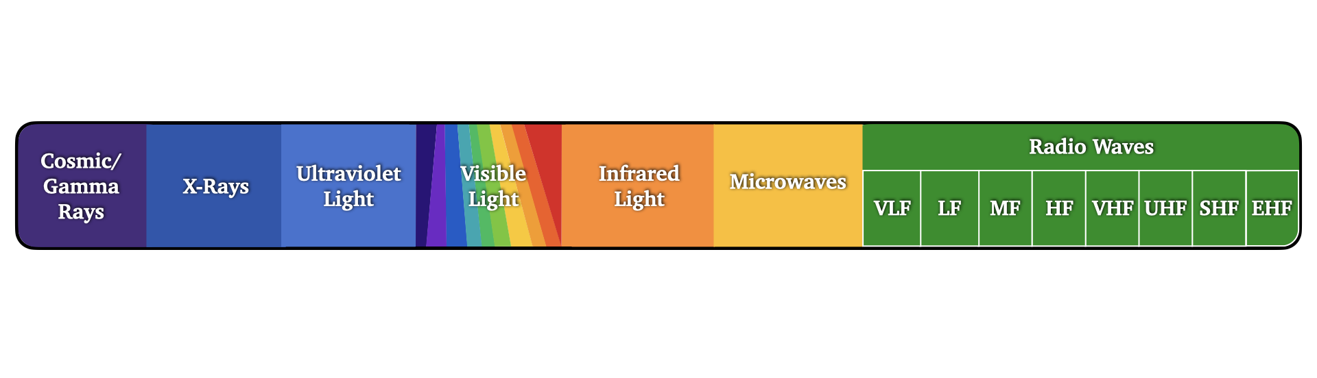
As you move from left to right across the spectrum above, wavelengths become longer and frequencies become lower. Compared to visible light, radio waves operate at much lower frequencies and much longer wavelengths.
Wavelength: the distance between two matching points on a wave.
Amplitude: the height or magnitude of a wave.
Frequency: the number of wave cycles that pass a fixed point each second.
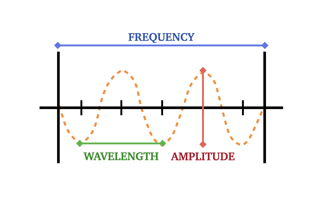
Frequency is measured in units called Hertz (Hz), which represent the number of wave cycles occurring each second. Radio frequencies span a very large range, from 3 kilohertz to 300 gigahertz.
| Unit | Equivalent |
|---|---|
| 1 Hertz (Hz) | 1 cycle per second |
| 1 Kilohertz (kHz) | 1,000 cycles per second |
| 1 Megahertz (MHz) | 1,000,000 cycles per second |
| 1 Gigahertz (GHz) | 1,000,000,000 cycles per second |
Because wavelength and frequency affect how radio signals travel and behave, radio frequencies are often grouped into frequency ranges. In amateur radio, HF, VHF, and UHF are three of the most commonly used frequency ranges.
| Range Name | Abbreviation | Frequency Range |
|---|---|---|
| Very Low Frequency | VLF | 3 kHz – 30 kHz |
| Low Frequency | LF | 30 kHz – 300 kHz |
| Medium Frequency | MF | 300 kHz – 3 MHz |
| High Frequency | HF | 3 MHz – 30 MHz |
| Very High Frequency | VHF | 30 MHz – 300 MHz |
| Ultra High Frequency | UHF | 300 MHz – 3 GHz |
| Super High Frequency | SHF | 3 GHz – 30 GHz |
| Extremely High Frequency | EHF | 30 GHz – 300 GHz |
HF (High Frequency)
- Long-distance communication
- Signals can reflect off the ionosphere
- Larger antennas
- Common for regional and worldwide contacts
VHF (Very High Frequency)
- Primarily line-of-sight communication
- Reliable local and regional coverage
- Commonly used for repeaters
- Includes the 2-meter amateur band
UHF (Ultra High Frequency)
- Primarily line-of-sight communication
- Better building penetration
- Shorter communication range
- Includes the 70-centimeter amateur band
Radio Components
Radios are made up of five main components.
1. Transmitter
A transmitter generates radio waves that carry information from one location to another. When someone speaks into a radio's microphone, the transmitter converts the sound of their voice into an electrical signal. That signal is encoded onto a carrier wave and sent to the antenna where it is radiated outward as radio waves.
2. Receiver
A receiver performs the opposite function of a transmitter. It captures incoming radio waves through the antenna and separates the information from the carrier wave. The receiver then converts that information back into usable audio or data, such as sound from a speaker or information displayed on a screen.
Some radios only receive signals. A common example is a car radio or a police scanner. Other radios, called transceivers, can both transmit and receive signals.
3. Antenna
An antenna allows a radio system to efficiently transmit and receive radio waves. During transmission, electrical energy is applied to the antenna, creating changing electric and magnetic fields that radiate outward as radio waves. During reception, the antenna captures radio waves from the surrounding environment and passes them to the receiver. Antenna size and design are often related to the frequency being used.
4. Feed Line / Transmission Line
A feed line, also called a transmission line, carries the radio frequency energy between the radio equipment and the antenna. Coaxial cable is one of the most common types of feed line used in radio systems. Proper feed lines help minimize signal loss and improve overall system performance.
5. Power Supply
A power supply provides the electrical energy needed to operate the radio equipment. Radio systems may be powered by batteries, vehicle electrical systems, generators, solar systems, or external power supplies. Reliable power is essential for both transmitting and receiving radio signals.
Modulation
Radio waves by themselves do not contain useful information. To send voice, data, images, or other information over radio waves, the information must first be added to a carrier wave. This process is called modulation.
Different types of modulation encode information by changing specific properties of a carrier wave. Some methods vary the wave’s amplitude (strength), while others vary its frequency or phase.
The type of modulation being used often determines the radio's operating mode.
Amplitude Modulation (AM)
Amplitude Modulation, or AM, works by changing the amplitude (strength) of the carrier wave while leaving the frequency unchanged.
As the audio changes, the height of the radio wave increases and decreases to carry the information.
AM signals can often travel long distances, especially on lower frequencies.
Single Sideband (SSB)
Single Sideband, or SSB, is a more efficient form of AM communication commonly used on HF amateur radio bands.
SSB works by transmitting only the portion of the signal needed to carry voice information. Because less power and bandwidth are used, SSB signals can communicate over very long distances more effectively than standard AM.
Most long-distance voice communication on the HF bands uses either Upper Sideband (USB) or Lower Sideband (LSB).
Frequency Modulation (FM)
Frequency Modulation, or FM, works by changing the frequency of the carrier wave while the amplitude stays mostly the same.
As the audio changes, the radio wave shifts slightly closer together or farther apart to carry the information.
FM signals generally provide clearer audio quality and are commonly used for VHF and UHF communications.
Antenna Design
Antenna size is closely related to wavelength and operating frequency.
In general:
- Lower frequencies require larger antennas
- Higher frequencies require smaller antennas
Many antennas are designed to be a fraction of the signal wavelength, such as:
- Quarter-wave antennas
- Half-wave antennas
This is one reason HF antennas are often much larger than VHF or UHF antennas.
Modes
An operating mode describes the method a radio uses to communicate information. Different modes are designed for different purposes such as voice communication, digital messaging, image transmission, or long distance communication.
Some modes are designed for clear local communication, while others are optimized for weak signals or efficient use of bandwidth.
| Operating Mode | Modulation Modes |
|---|---|
| Analog Voice | FM, AM, SSB, PM, ISB, DSB-SC |
| Digital | AMTOR, Hellschreiver, Multi Tone 63 (MT63), MFSK (JT65, FT8 etc), Packet Radio/AX25 (AMPRNet & APRS), Phase-Shift Keying (PSK31 etc), Frequency-Shift Keying/Radioteletype (RTTY) |
| Digital Voice | DMR, D-STAR, System Fusion, P25, NXDN, M17 |
| Image/Video | Slow Scan TV (SSTV), Fast Scan TV (FSTV-NTSC standard) |
| Morse Code | Continuous Wave (CW), Modulated Continuous Wave (MCW), Frequency-Shift Keying (FSK) |
Procedural Activities (Modes): EchoLink, Earth-Moon-Earth (EME), Automatically Controlled Digital Stations (ACDS), OSCAR, Low transmitter power (QRP), ALS, ALE
Digital Modes
Digital modes allow radios to transmit information such as text, images, location data, and computer-generated signals using radio waves. Instead of transmitting only voice, digital modes convert information into digital data that can be transmitted and decoded by radios, computers, or specialized equipment.
Different digital modes are designed for different purposes. Some are optimized for weak-signal communication over long distances, while others are used for messaging, position reporting, emergency communications, or digital voice.
Digital modes are widely used in modern amateur radio because they can often maintain usable communication in conditions where analog voice becomes noisy or difficult to understand.
Popular Digital Phone Modes
Digital phone modes transmit digitally encoded voice instead of traditional analog FM audio. These systems often provide clearer audio, identification features, messaging capabilities, and improved spectrum efficiency.
Many digital voice systems also support repeater networking, allowing operators to communicate across large geographic areas using linked repeater systems or internet-connected networks.
Popular digital phone modes include:
- DMR (Digital Mobile Radio) — Widely used in amateur and commercial radio systems
- D-STAR — Developed by the Japan Amateur Radio League (JARL) and adopted by Icom
- System Fusion (C4FM) — Developed by Yaesu
- P25 (Project 25) — Commonly used by public safety agencies
Because many digital voice systems use different protocols, radios are often only compatible with specific digital modes.
APRS
APRS (Automatic Packet Reporting System) is a digital modulation mode used to transmit real-time information over radio.
APRS is commonly used for:
- Position and GPS tracking
- Short text messaging
- Weather station reporting
- Emergency communications
- Tactical location tracking during events
Most APRS activity in North America occurs on 144.390 MHz using packet radio.
APRS allows operators to share information with nearby stations, digipeaters, internet gateways, and mapping systems in real time.
Propagation
Propagation refers to the way radio signals travel through the environment. Frequency, terrain, atmospheric conditions, obstacles, antennas, and polarization all affect how radio signals behave.
Radio signals can travel in several different ways depending on the frequency and surrounding conditions. Some signals travel primarily in straight lines, while others can reflect, refract, or bend around obstacles.
Understanding propagation helps radio operators choose appropriate frequencies, antennas, and operating methods for different communication situations.
Line-of-Sight Propagation
Most VHF and UHF communications rely on line-of-sight propagation. Signals generally travel best when there is a clear, unobstructed path between stations.
Terrain, buildings, trees, and other obstacles can block or weaken signals. Increasing antenna height often improves communication range because it extends the radio horizon.
Common examples of line-of-sight communication include:
- Handheld radios
- Mobile radios
- Repeaters
- Public safety communications
- Most VHF and UHF amateur radio operations
Ground Wave Propagation
Ground wave propagation occurs when radio signals follow the curvature of the earth. Lower-frequency signals, especially in the LF and MF ranges, can travel significant distances using ground wave propagation.
Ground wave signals are commonly used for:
- AM broadcast radio
- Maritime communications
- Navigation systems
- Some military communications
Ground conductivity, terrain, and frequency all affect ground wave performance.
Skywave Propagation
Skywave propagation occurs when radio signals are refracted by the ionosphere back toward the earth. This allows some HF signals to travel hundreds or even thousands of miles beyond the horizon.
Skywave propagation is strongly affected by:
- Time of day
- Solar activity
- Frequency
- Season
- Atmospheric conditions
HF operators often use skywave propagation for long-distance communication.
Diffraction
Diffraction occurs when radio waves bend around obstacles such as mountains, hills, or buildings.
Lower frequencies generally diffract more effectively than higher frequencies. This is one reason VHF signals often travel farther than UHF signals in mountainous terrain.
Diffraction can allow communication even when stations do not have a perfect line of sight.
Reflection
Reflection occurs when radio waves bounce off surfaces such as buildings, mountains, metal structures, or atmospheric layers.
Reflected signals can sometimes improve communication range, but they can also create multipath interference where multiple versions of the same signal arrive at different times.
Reflection is commonly observed in:
- Urban environments
- Indoor radio communications
- Satellite communications
- HF skywave propagation
Refraction
Refraction occurs when radio waves bend as they pass through areas of the atmosphere with different densities or electrical properties.
Atmospheric refraction can slightly extend the radio horizon beyond normal line-of-sight distances. Under certain weather conditions, signals may travel unusually long distances through tropospheric ducting.
Polarization
Polarization: the orientation of the radio wave's electric field relative to the earth.
Common types of polarization include:
- Vertical
- Horizontal
- Circular
For best performance, transmitting and receiving antennas should use the same polarization.
Most handheld and mobile amateur radio communications use vertical polarization because vertical antennas are practical for portable and vehicle-mounted operation.
Horizontal polarization is commonly used for many HF and weak-signal communications.
Circular polarization is commonly used in satellite communications because it helps compensate for changes in antenna orientation during operation.
A mismatch in polarization can significantly reduce signal strength and communication quality.
Interference & Noise
Radio signals can be affected by both natural and man-made interference.
Common interference sources include:
- Power lines
- Electronics
- Motors
- Atmospheric noise
- Buildings and terrain
Interference can reduce signal quality, create static, or make communication difficult.
Simplex vs. Duplex
Simplex uses a single frequency for both transmitting and receiving.
Duplex uses separate transmit and receive frequencies. This is commonly used with repeaters.
Repeaters
Repeaters help extend communication range.
A repeater works by receiving a signal on one frequency and retransmitting it on another frequency. Separate frequencies are used because the repeater’s transmitted signal would overpower its receiver if both operated on the same frequency at the same time.
Repeaters are often placed at elevated locations such as mountaintops, towers, or tall buildings to improve coverage. Many repeaters also transmit at higher power levels than handheld radios, allowing signals to travel much farther than direct radio-to-radio communication.
Input Frequency: The frequency your radio transmits on.
Output Frequency: The frequency your radio listens on.
Offset: The difference between repeater input and output frequencies. An offset can be positive or negative.
Tone (CTCSS / PL Tone): Some repeaters require an access tone before they will retransmit a signal. If the correct tone is not used, the repeater will ignore the transmission. Access tones help prevent interference between nearby repeaters using the same frequencies or offsets.
A courtesy tone is a brief tone transmitted after a station unkeys.
It indicates:
- The repeater is ready for the next station
- The previous transmission has fully cleared
Listening for the courtesy tone and pausing briefly before transmitting again helps prevent doubling and allows other stations time to break in.
Some repeaters remain keyed briefly after transmission ends. This is called hang time. Hang time helps conversations flow more smoothly and reduces repeated key-up delays.
Many repeaters include a time-out timer to prevent excessively long transmissions. If a station transmits too long, the repeater may stop retransmitting until the timer resets. To avoid this, keep your transmissions concise.
Basic Radio Controls
Volume
Controls received audio level.
Set the volume high enough to hear clearly without making the audio uncomfortable or distorted.
Squelch
Squelch mutes background receiver noise when no signal is present.
Proper squelch setting:
- High enough to eliminate unwanted noise
- Low enough to avoid blocking weak signals
If squelch is set too high, weak stations may not be heard. Not all radios include squelch control.
RF Gain
RF Gain controls receiver sensitivity.
Higher gain:
- Better weak-signal reception
- More noise may be heard
Lower gain:
- Less interference
- Reduced weak-signal reception
Not all radios include RF Gain control.
Mic Gain
Mic Gain controls transmitted audio strength.
Improper settings may cause:
- Weak audio
- Distorted audio
- Overdriven audio
Use moderate settings unless adjustment is needed.